LINE TRACKER
This was my first project and i did it when i was in my first year of graduation.Line tracker is a best way to put your hand into robotics.In this post i will teach you to make a line tracker along with the advanced PID controller.
Firstly we define a line tracker: It is a robot which follows a line.So we need to program a robot to track line. To do this we need to give some kind of input to the robot to let it know where the line is .This is where line sensors come in .And to drive the robot we need some kind of actuators(motors).
Materials required
Mechanical:
2 DC geared motors 100rpm Rs 125 each
2 L shaped clamps to hold motors Rs 15 each
1 Castor wheel Rs 15
some wood or acrylic or aluminium to build a chassi .( For my first bot i used a plastic box)
Electronics:
Dev board
1 Atmega16 microcontroller
1 40 pin mount
berg strips
connecting wires
paraller port connector DB25 male
330 ohms resistor
IC 7805
IC L293D
PCB
Sensor Board
8 pair of IR (Tx ,Rx)
330 ohms resistor
10k ohms resistor
PCB
Circuit Diagram

D ( 1 3 5 7 9 11) - tx ; D ( 2 4 6 8 10) - Rx ; R ( 1 3 5 7 9 11) - 330 ohms ; R ( 2 4 6 8 10) - 10Kohms ;
In the above circuit the first one is transmitter circuit and below we have receiver circuit.
The transmitter and receiver should be placed one below other.
Working:
A transmitter is a simple infrared led .It emits infrared light when forward biased.
While the receiver is a photo diode it is used in reverse biased state.when infra red light falls on it the resistance across the reverse biased diode decreases. This property is used to detect white and black surface.Now consider your sensor pair ( Tx and Rx) is on white line , in this case the IR light emitted by Led is completely reflected back by white surface and this light falls on Rx due to which the resistance across Rx decreases .And the output(lf,l2,l1,r1,r2,rf) vary i.e. under normal conditions the resistance of Rx is infinity therefore the voltage across 10k resistance may be close to 0V.And when IR light falls; it may increase as the diode resistance decreases drastically and becomes comparable to 10k .
With the above information we can fairly judge the o/p under white and black surfaces.
Black : o/p will be high
white : o/p will be low
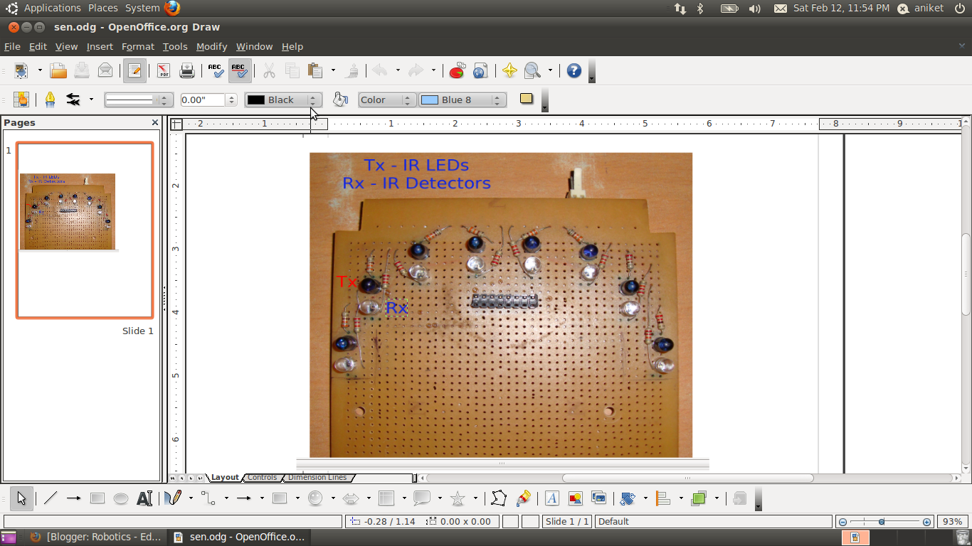
Here are some pictures of sensor board.These pictures are of different sensor board.It has 8 sensor pair but there is never a need of 8 sensor 6 should suffice for us.


Ok ! Now we are done with sensor board its time to test it .How to test it ?
Its really simple take a mutimeter connect one end(black) to gnd other(Red) to sensor output (use multimeter in voltage measuring mode select voltage range below 10/20 V).
Now measure the value of output with your hands on the sensor(make sure your hands be just above the sensors and very close to them around 1cm above), lets call it V1.Now remove your hands completely and let the area above the sensors be open and take the reading, let it be V2.
The sensors work properly if there is a substantial difference between V1 and V2 .V1 sould always be greater than V2. And V1-V2 should be approx around 1 volt.But this may differ with the environment . You may get false readings if you test this in sunlight.Sunlight contains a lot of IR light .So if you are facing problems during day and everything works fine at night then sunlight is the only problem.The only solution is to cover the sensors.
The above board has 8 sensors but its not necessary we can use 4 or 6 of them and follow a line perfectly well.
Now moving to drive system .We will be needing a Motor driving Circuit to drive the 2 motors of the robot.
You can google for more info about the motor driver circuit. I used L293D as driving IC. It is a simple H bridge driving circuit.
The IC can drive 2 motors. and takes 4 inputs 2 for each . Which lets motor control in both directions.
And finally we have a micro controller which does the part of controlling the motor depending on the inputs from the Sensor board.
https://docs.google.com/open?id=0B7lDtwez94H3ZWUxNDM0MjktNjE5Mi00ZDFhLWI2ZTAtZjI4MmUwZDcwMzFh
This was my first project and i did it when i was in my first year of graduation.Line tracker is a best way to put your hand into robotics.In this post i will teach you to make a line tracker along with the advanced PID controller.
Firstly we define a line tracker: It is a robot which follows a line.So we need to program a robot to track line. To do this we need to give some kind of input to the robot to let it know where the line is .This is where line sensors come in .And to drive the robot we need some kind of actuators(motors).
Materials required
Mechanical:
2 DC geared motors 100rpm Rs 125 each
2 L shaped clamps to hold motors Rs 15 each
1 Castor wheel Rs 15
some wood or acrylic or aluminium to build a chassi .( For my first bot i used a plastic box)
Electronics:
Dev board
1 Atmega16 microcontroller
1 40 pin mount
berg strips
connecting wires
paraller port connector DB25 male
330 ohms resistor
IC 7805
IC L293D
PCB
Sensor Board
8 pair of IR (Tx ,Rx)
330 ohms resistor
10k ohms resistor
PCB
Circuit Diagram

D ( 1 3 5 7 9 11) - tx ; D ( 2 4 6 8 10) - Rx ; R ( 1 3 5 7 9 11) - 330 ohms ; R ( 2 4 6 8 10) - 10Kohms ;
In the above circuit the first one is transmitter circuit and below we have receiver circuit.
The transmitter and receiver should be placed one below other.
Working:
A transmitter is a simple infrared led .It emits infrared light when forward biased.
While the receiver is a photo diode it is used in reverse biased state.when infra red light falls on it the resistance across the reverse biased diode decreases. This property is used to detect white and black surface.Now consider your sensor pair ( Tx and Rx) is on white line , in this case the IR light emitted by Led is completely reflected back by white surface and this light falls on Rx due to which the resistance across Rx decreases .And the output(lf,l2,l1,r1,r2,rf) vary i.e. under normal conditions the resistance of Rx is infinity therefore the voltage across 10k resistance may be close to 0V.And when IR light falls; it may increase as the diode resistance decreases drastically and becomes comparable to 10k .
With the above information we can fairly judge the o/p under white and black surfaces.
Black : o/p will be high
white : o/p will be low
Here are some pictures of sensor board.These pictures are of different sensor board.It has 8 sensor pair but there is never a need of 8 sensor 6 should suffice for us.


Ok ! Now we are done with sensor board its time to test it .How to test it ?
Its really simple take a mutimeter connect one end(black) to gnd other(Red) to sensor output (use multimeter in voltage measuring mode select voltage range below 10/20 V).
Now measure the value of output with your hands on the sensor(make sure your hands be just above the sensors and very close to them around 1cm above), lets call it V1.Now remove your hands completely and let the area above the sensors be open and take the reading, let it be V2.
The sensors work properly if there is a substantial difference between V1 and V2 .V1 sould always be greater than V2. And V1-V2 should be approx around 1 volt.But this may differ with the environment . You may get false readings if you test this in sunlight.Sunlight contains a lot of IR light .So if you are facing problems during day and everything works fine at night then sunlight is the only problem.The only solution is to cover the sensors.
The above board has 8 sensors but its not necessary we can use 4 or 6 of them and follow a line perfectly well.
Now moving to drive system .We will be needing a Motor driving Circuit to drive the 2 motors of the robot.
You can google for more info about the motor driver circuit. I used L293D as driving IC. It is a simple H bridge driving circuit.
The IC can drive 2 motors. and takes 4 inputs 2 for each . Which lets motor control in both directions.
And finally we have a micro controller which does the part of controlling the motor depending on the inputs from the Sensor board.
No comments:
Post a Comment